FAQ
What is a PCB?
What is a PCB?
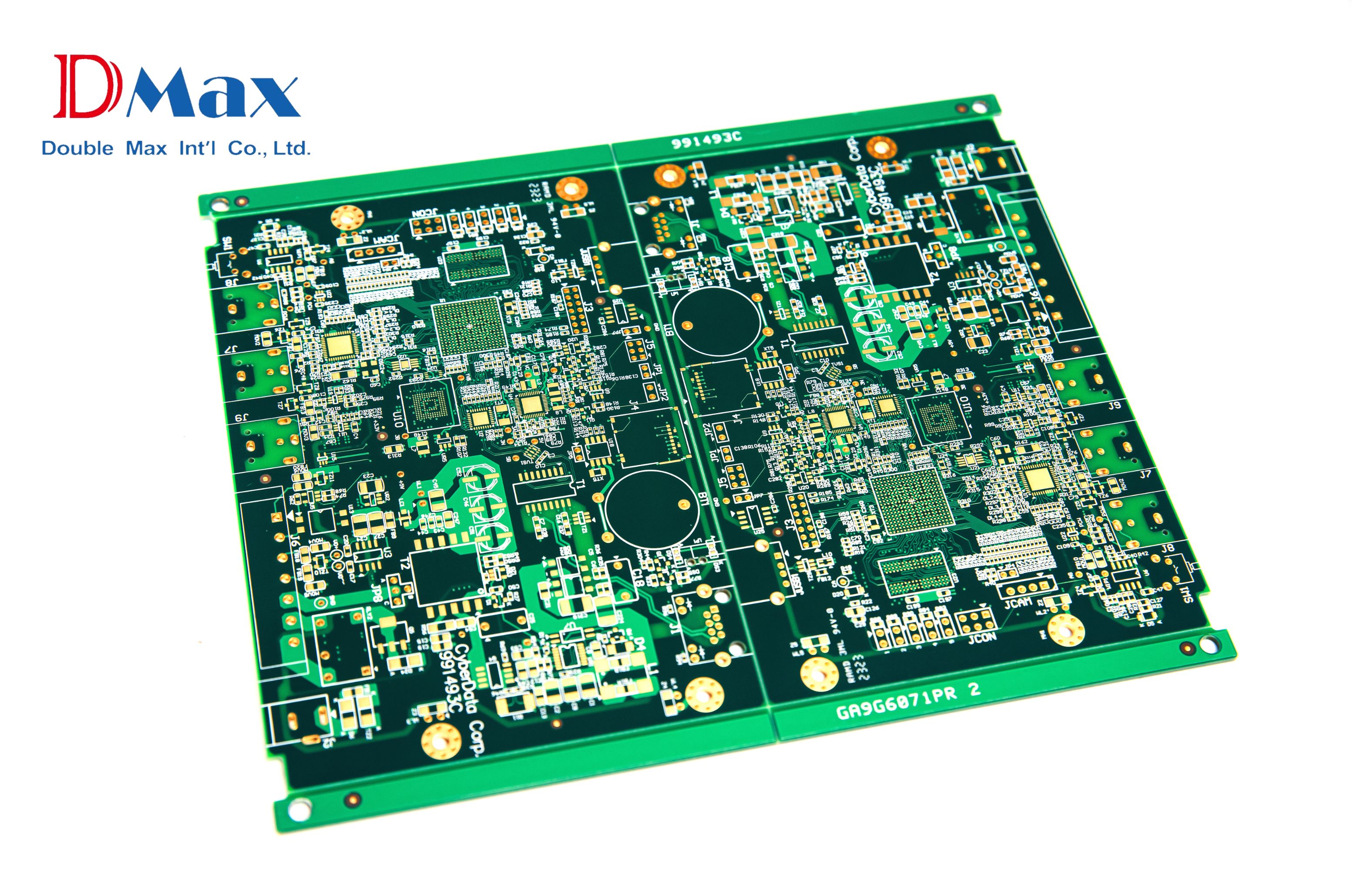
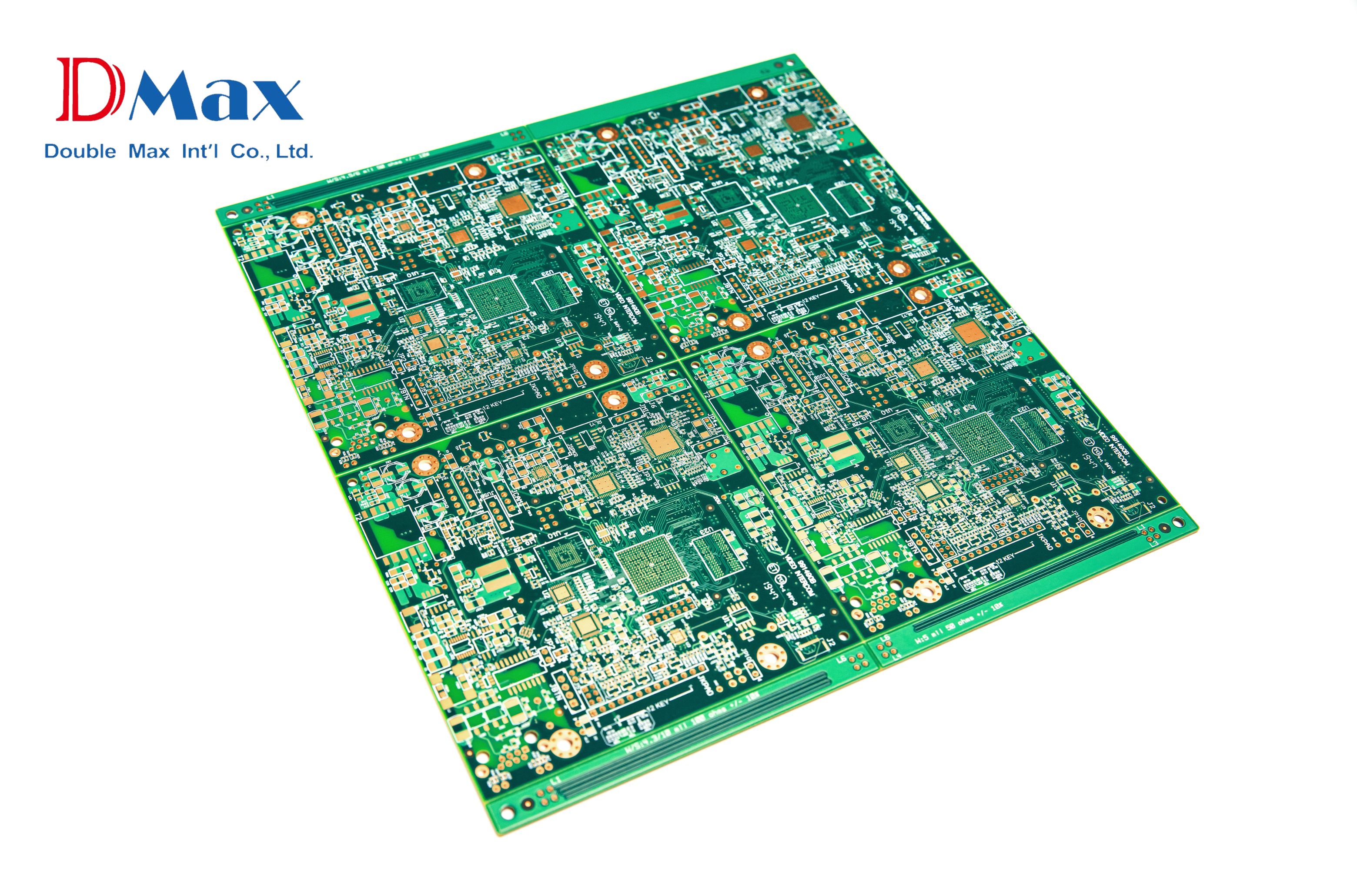
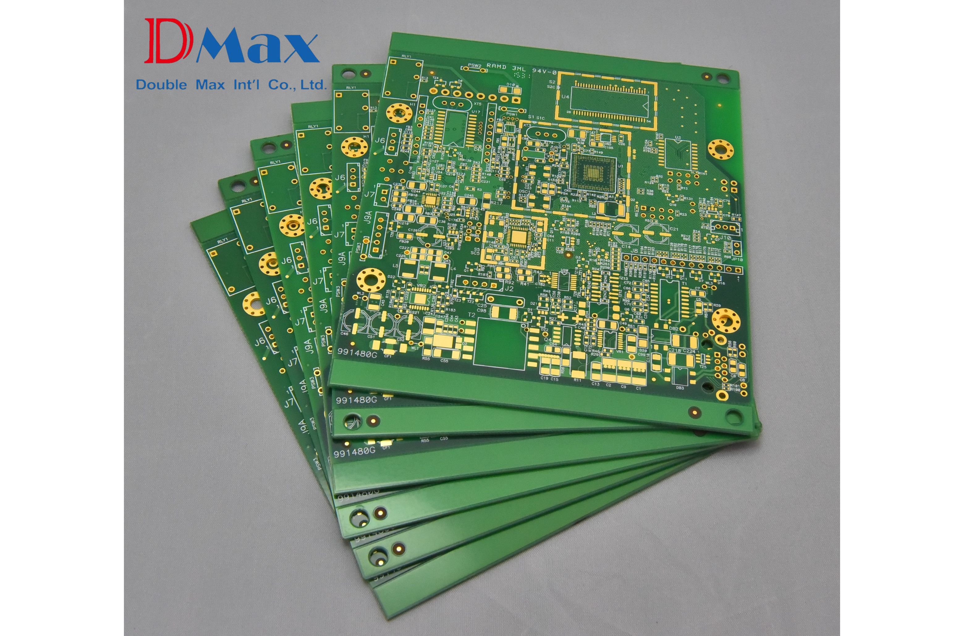
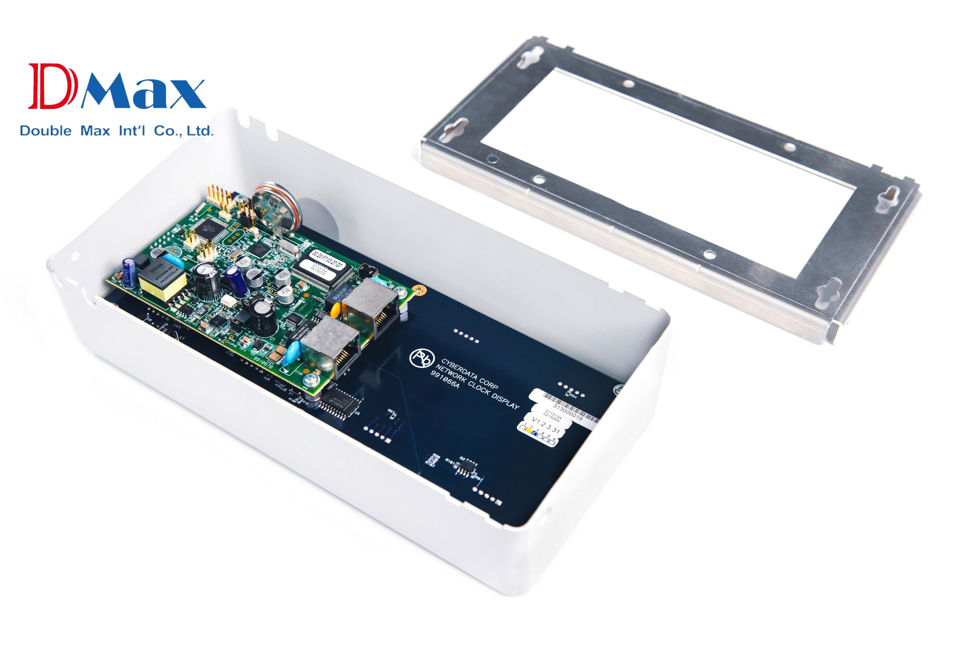
PCB stands for Printed Circuit Board. A PCB is a board made of insulating material (most commonly fiberglass, such as FR-4), onto which a pre-designed conductive pattern of copper foil (traces) and component mounting locations (pads) are "printed" or "etched".
A PCB typically refers to a "bare board." This means a PCB is a board that has not yet had any electronic components installed. At this stage, the PCB does not have any electronic function or utility. The next critical step it must undergo is "PCBA (Printed Circuit Board Assembly)" to make the PCB function correctly.
PCB (Printed Circuit Board)
- Common Aliases: Bare Board, Empty Board, Substrate.
- Status: A PCB is a "base board" (substrate) on which no electronic components have yet been mounted. A PCB only has the copper traces (for conducting electricity) and pads (for positioning components) "printed" onto it according to the circuit design files.
- Function: A PCB itself does not have any electronic function. The sole purpose of a PCB is to serve as a platform (or skeleton) to "support" the components that will be mounted later and to "provide" the electrical connection paths between those components.
What are the core functions of a PCB?
1. Mechanical Support: A PCB provides a rigid foundation to secure all electronic components in their correct positions.
2. Electrical Connection: Through the complex copper traces on the board, a PCB replaces messy traditional wires, providing reliable, high-density electrical connections between all components (such as ICs, resistors, and capacitors).
What key PCB design points affect PCBA component selection and assembly?
The PCB is the "foundation" of the PCBA. The design of this foundation directly determines whether the components subsequently assembled on the PCB can be mounted accurately and securely.
If you can consider the PCBA assembly process in advance when designing your PCB, you can significantly improve the yield, reliability, and reduce the cost of future PCBA mass production.
Here are the four key PCB design considerations that are critical for PCBA assembly:
1. Footprint / Land Pattern Design
-
This is the most critical point. A footprint (or land pattern) is the copper contact point on the PCB used for soldering a component.
-
The footprint pattern on the PCB must 100% accurately match the recommendations in the datasheet for every single component on your BOM list.
-
If the design is wrong (e.g., pads are too large, too small, or incorrectly spaced), it will directly cause severe soldering defects during the PCBA's SMT reflow process, such as:
-
Tombstoning: One end of a small component (like a resistor) lifts off the pad.
-
Bridging: Solder connects adjacent pins of a fine-pitch IC.
-
Open Circuit: A PCBA component pin fails to solder to its pad.
-
2. Component Spacing & Layout
-
The component "layout" on the PCB cannot only consider the electrical function of the PCBA components; it must also consider the actual physical assembly space on the PCB substrate.
-
Here are two key PCB design points to watch:
-
SMT Placement Space: High-speed pick-and-place machines need physical space for their nozzles to place PCBA components. If PCBA components (especially those with large size differences) are placed too close together, it can prevent the machine from placing them accurately or cause it to collide with an adjacent component.
-
Soldering Process Considerations:
-
DIP Insertion (Wave Soldering): If DIP (through-hole) components (like a USB connector) are too close to SMT components, the SMT components may be damaged or washed away by the high-temperature solder wave (a common "wave soldering" issue).
-
Rework Space: Sufficient space must be reserved so that if a PCBA fails, technicians have room to de-solder and replace specific components.
-
-
3. Solder Mask
-
The function of the PCB solder mask (the green, black, etc., layer) is to "precisely expose the solder pads while covering all other traces." Therefore, the "opening" (aperture) accuracy of the PCB solder mask is crucial.
-
If this stage of the PCB design is flawed, it can lead to:
-
Solder Mask Encroachment: This causes the solderable area of the PCB pad to shrink, resulting in insufficient PCBA solder joint strength or open circuits.
-
Missing Solder Dam: Between the pads of high-density, fine-pitch ICs on a PCB, a solder mask "dam" is required. If this dam breaks because it was designed too thin, solder will flow and bridge the pads during reflow, causing a short circuit.
-
4. Thermal Management and Heat Dissipation Design
-
If your BOM includes high-performance, high-power (high-heat) PCBA components (like CPUs, FPGAs, power ICs), your PCB design itself must incorporate corresponding heat dissipation functions.
-
Therefore, the PCB must be designed with large copper areas (as heat sinks), thermal vias, or reserved space to install external heat sinks.
-
If the design is flawed, the PCB's heat dissipation capability will be insufficient. When the PCBA operates, these high-power components will immediately overheat, leading to performance degradation, system crashes, or even component burnout.
RECOMMENDATIONS



















_2_cover.png)


_cover.png)


