FAQ
What is DIP? How is DIP technology applied in PCBA manufacturing?
What is DIP? How is DIP technology applied
in PCBA manufacturing?
DIP stands for Dual In-line Package. However, in the PCBA manufacturing field, DIP more often represents an "assembly process," which we call "insertion technology" or "Through-Hole Technology (THT)."
DIP is the "traditional" method of electronic assembly. Before SMT (Surface-Mount Technology) became the mainstream, all PCBAs were completed using DIP.
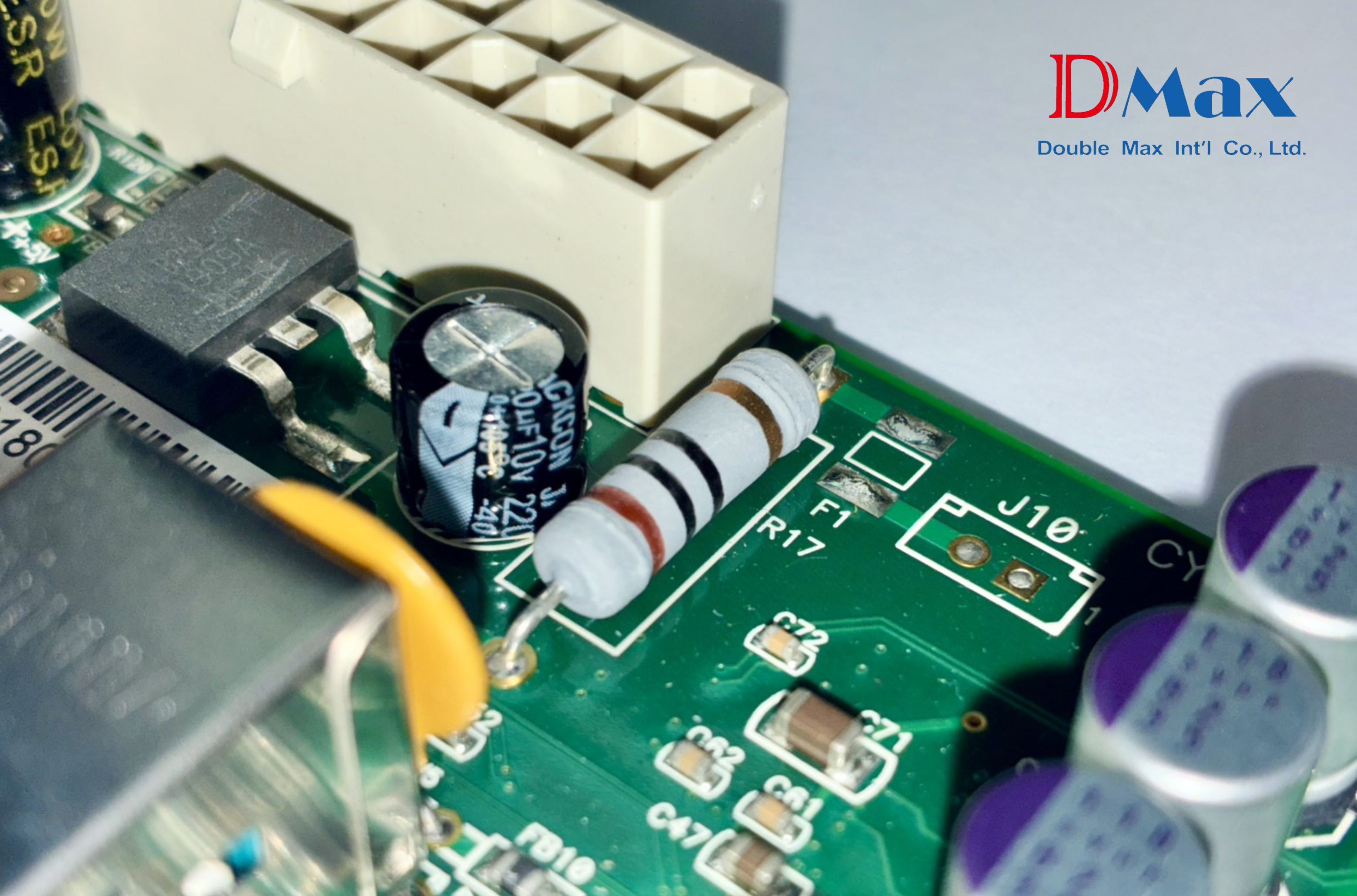
Its core concept is the complete opposite of SMT, which "mounts" components on the surface. DIP components have long metal "leads" (commonly called "legs"). During assembly, these leads must be "inserted through" the pre-drilled "through-holes" on the bare PCB. They are then soldered on the other side of the PCB to complete the assembly.
The Key Difference Between DIP and SMT
To understand DIP, you must first understand its fundamental differences from SMT:
SMT (Surface-Mount Technology)
- Features: Components are tiny, leadless (or have flat-lying leads).
- Process: "Mounted" on the same side of the PCB surface, soldered using a "Reflow Oven" to heat solder paste.
- Applications: High-density, miniaturisation, high-frequency signals (e.g., ICs, resistors, capacitors).
DIP (Insertion Technology)
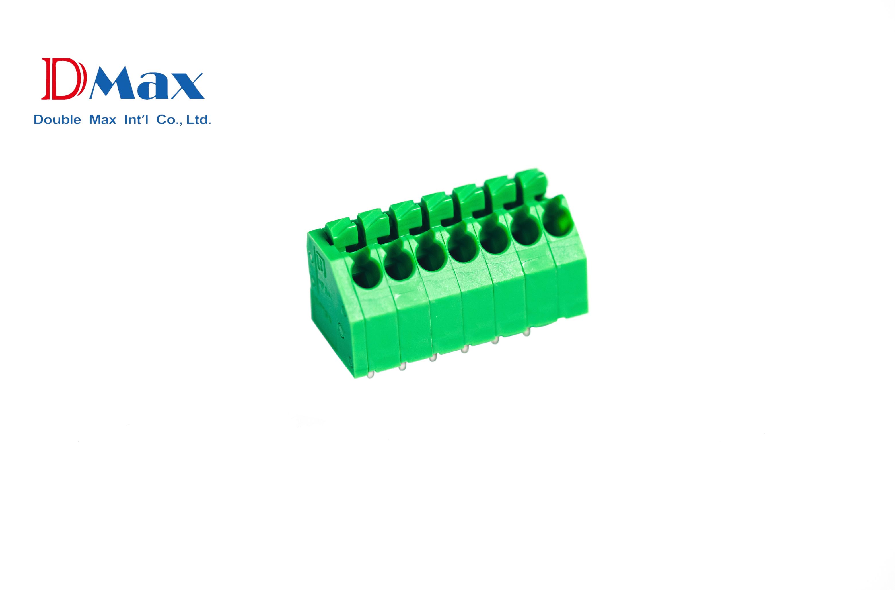
- Features: Components are larger, have long leads ("legs").
- Process: "Inserted through" the PCB's through-holes, soldered on the other side of the board using "Wave Soldering" or "manual soldering."
- Applications: Components requiring high mechanical strength, high power, or special form factors.
Why do modern PCBAs still "critically need" DIP?
Since SMT is so advanced, why do we still need DIP?
Because on a PCBA, there are many critical components that SMT cannot replace. DIP exists to "complement" SMT, making up for SMT's deficiencies in "physical strength" and "power handling."
DIP's applications are concentrated in the following three main areas:
1. Demanding "Superior Mechanical Strength"
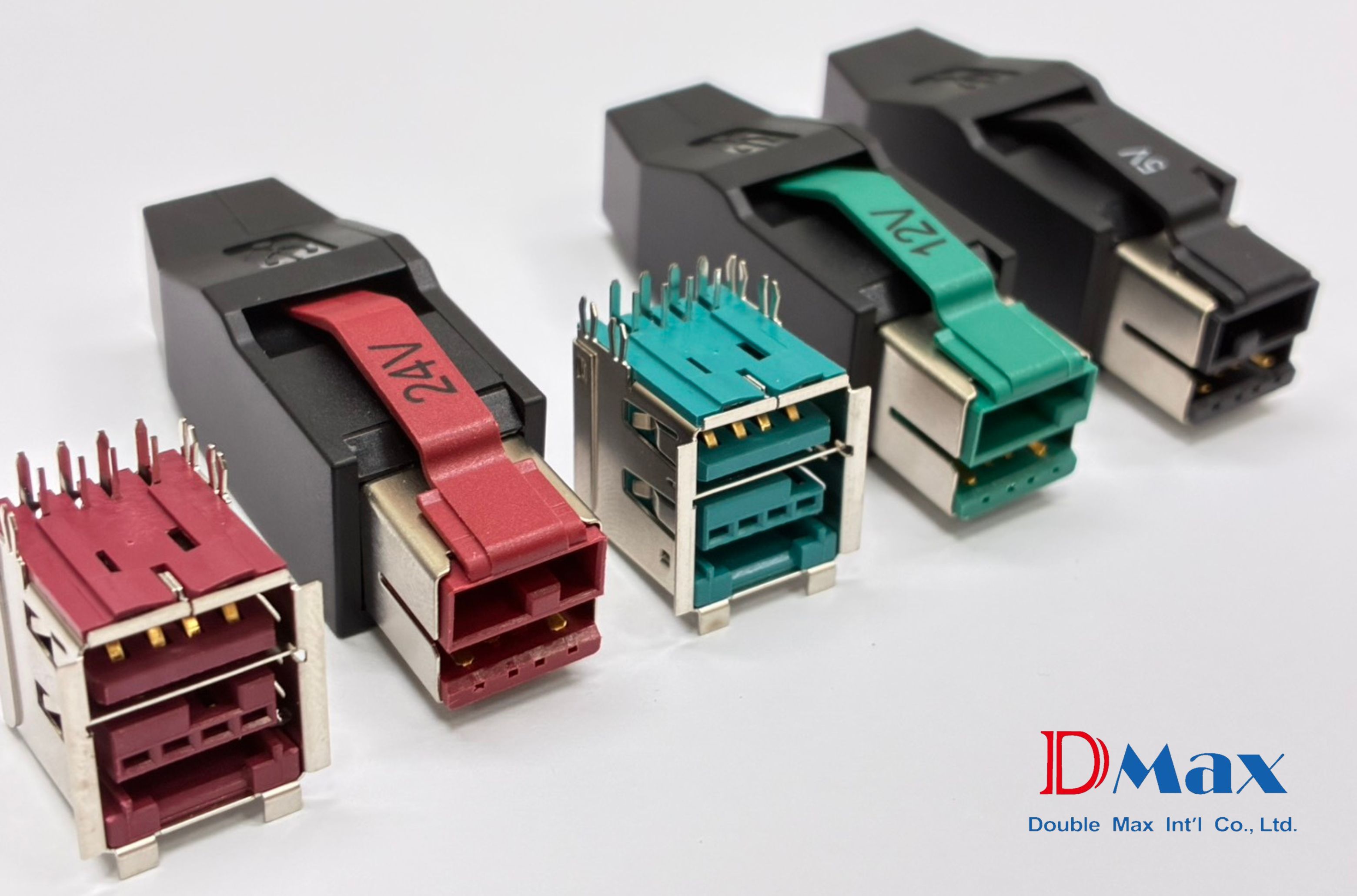
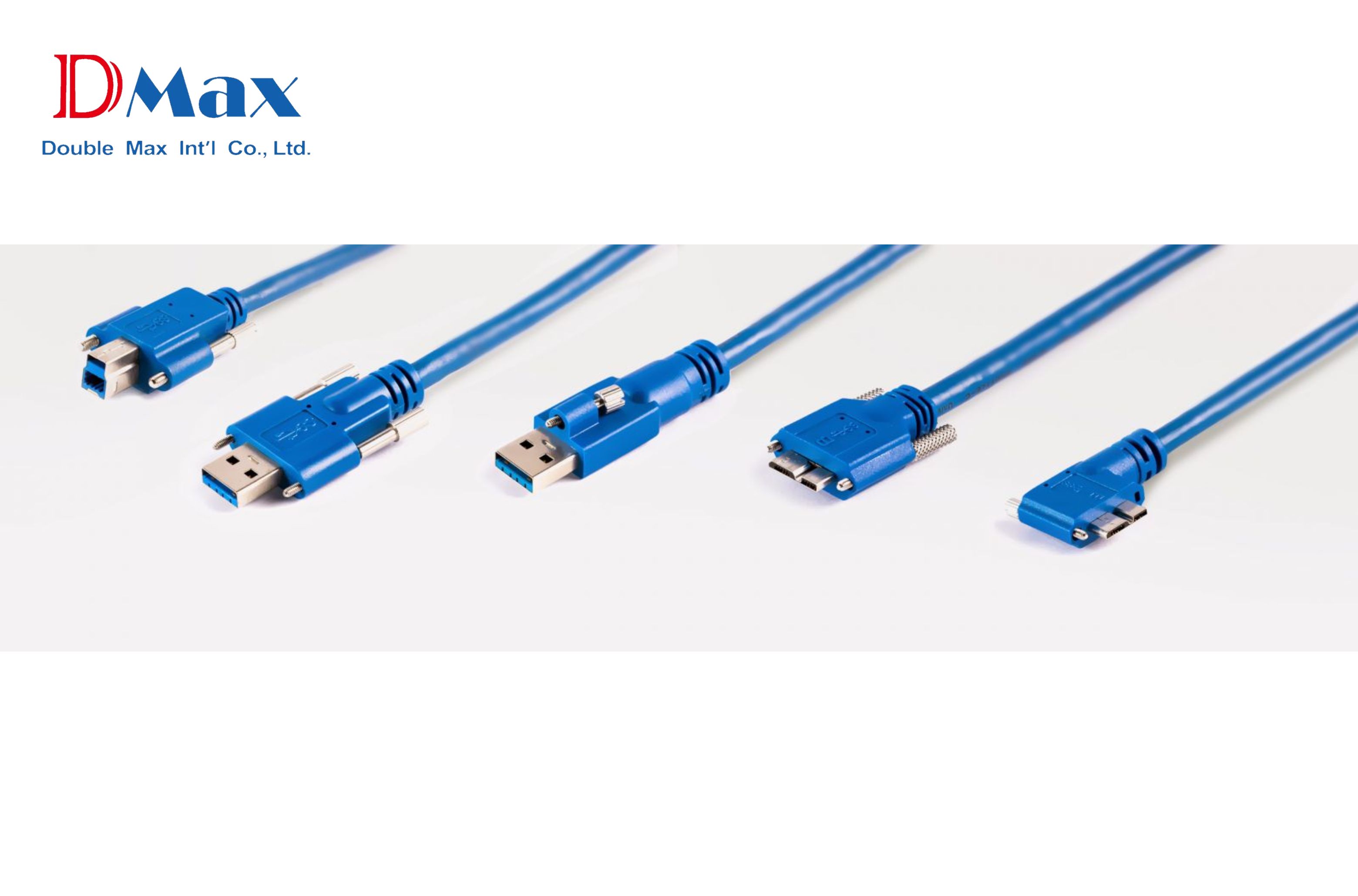
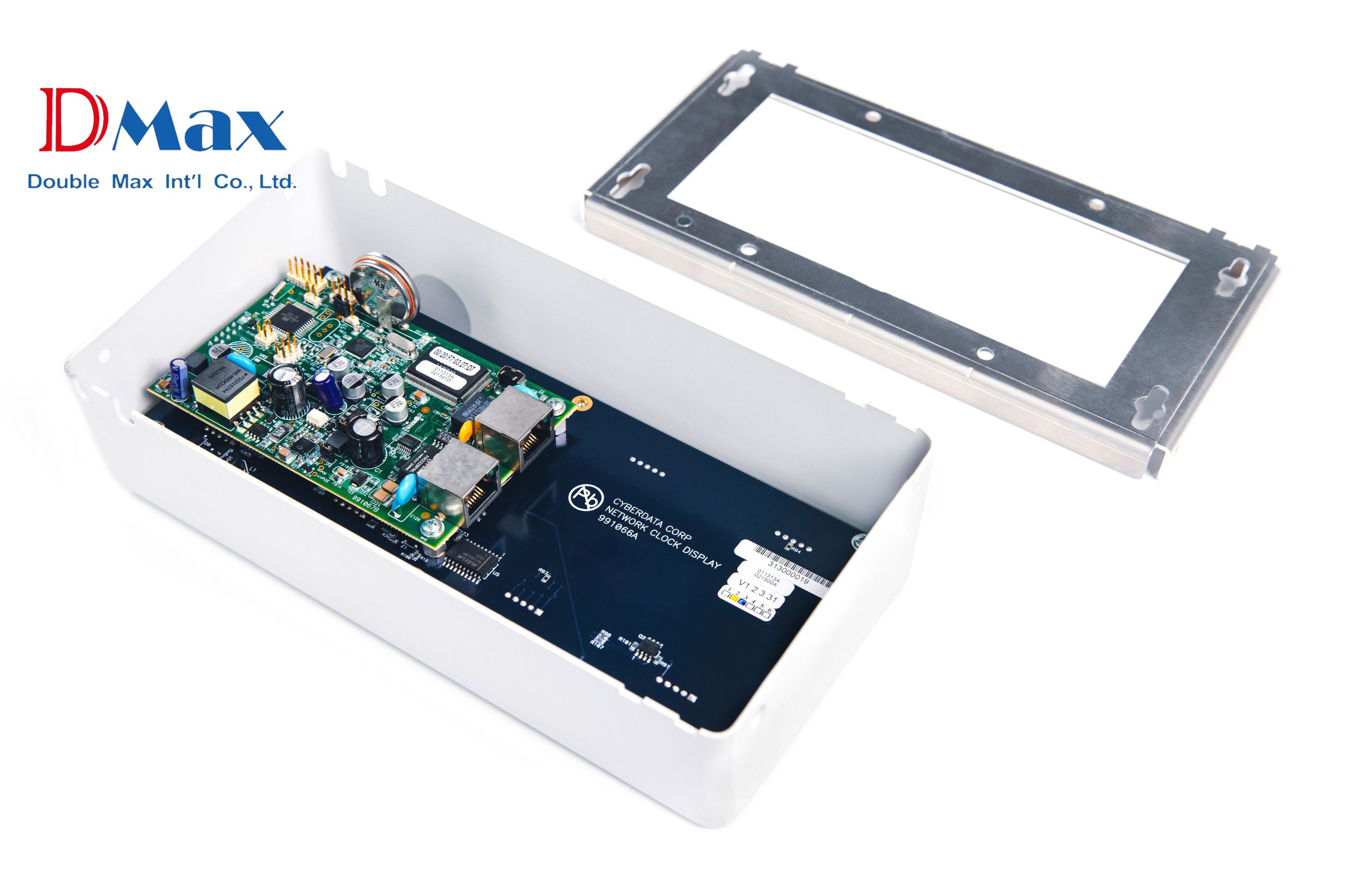
Applications: Connectors (e.g., USB ports, HDMI, RJ45 jacks, power inlets).
Logic: These components must withstand daily user "plugging/unplugging," "twisting," and "stress." An SMT component, held only by a "surface" solder joint, is absolutely incapable of withstanding this type of physical force. A DIP component's leads, which "pass through" the PCB and are soldered, are like roots deep in the soil. Their physical bond strength is far superior to SMT.
2. Handling "High Power," "High Current," and "High Heat"
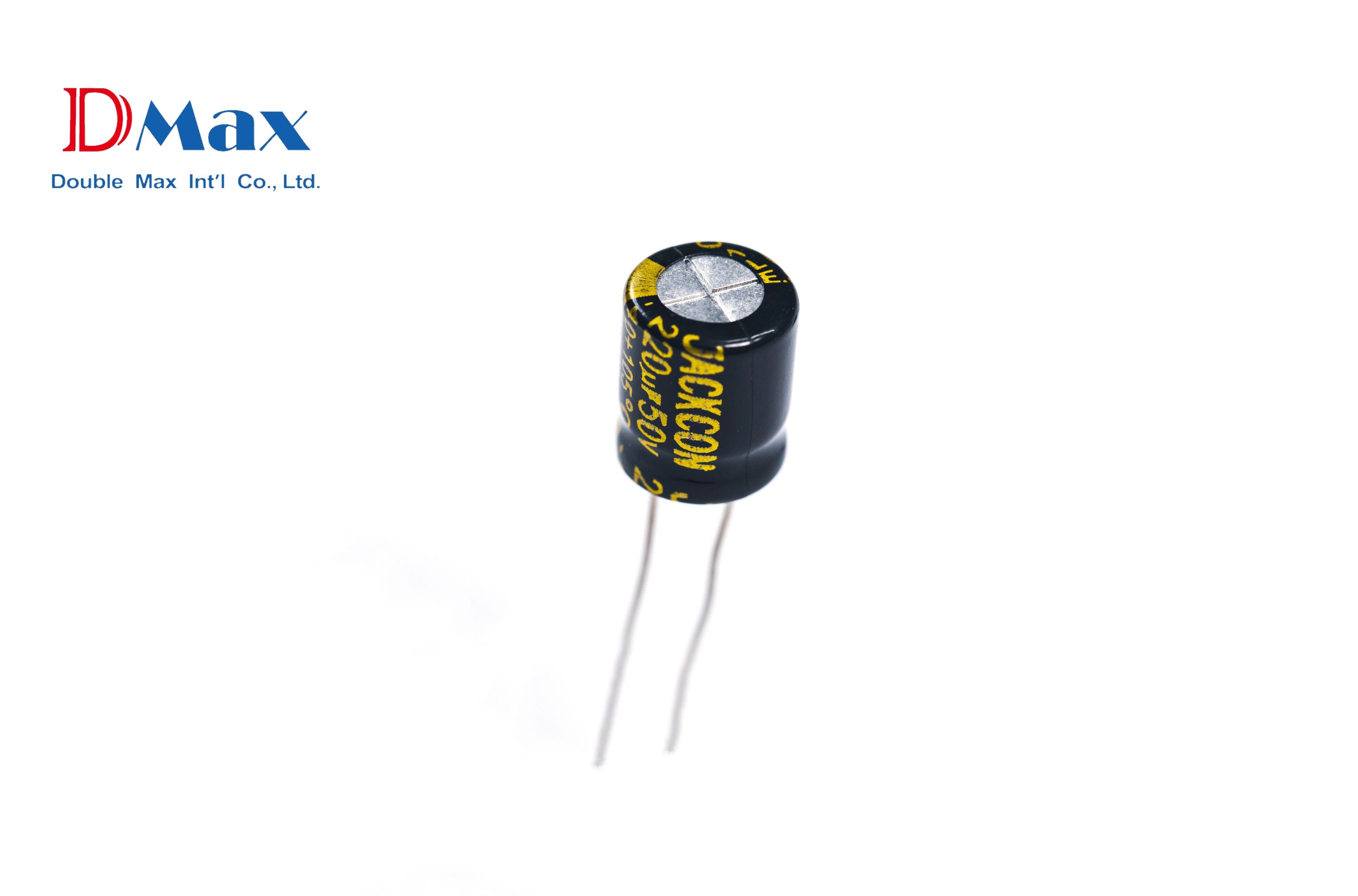
Applications: Large electrolytic capacitors, transformers, inductors, power transistors, fuse holders.
Logic: These components are bulky and heavy; SMT joints cannot support them. More importantly, they need to transmit high voltage or high current and generate significant heat. DIP's robust leads and through-hole design provide a larger cross-sectional area for conductivity and a better path for heat dissipation.
3. Assembling "Special Form Factor" Components
Applications: Potentiometers (variable resistors), push-button switches, buzzers, some sensors.
Logic: SMT is designed for standardized components packaged in "tape-and-reel." Many special-function components do not have an SMT version and can only be flexibly assembled onto the PCBA via DIP (often through manual insertion).
The Core DIP Process (The "Logic")
In modern PCBA manufacturing, the DIP process is typically performed after the SMT process. This is called "Mixed-Technology."
SMT Completion: The PCBA first completes all SMT placement and reflow soldering.
Insertion: D-MAX's professional line operators, following a "Standard Operating Procedure (SOP)," manually or semi-automatically insert the DIP components (like connectors, capacitors) into the correct holes on the PCB.
Wave Soldering: This is the core soldering step for DIP.
Method: The inserted PCBA (often placed in a special "carrier" to protect the SMT components) is passed over a "wave" of molten solder.
Purpose: The solder wave instantly flows up the protruding leads, soldering all DIP components at once.
Touch-up & Trimming:
After machine soldering, QC personnel inspect for any missed or bridged joints. Skilled technicians then perform "manual touch-up soldering" to ensure 100% solder joint quality, while also trimming any excessively long leads.
How does D-MAX execute DIP?
DIP quality is highly dependent on "process control" and "personnel skill."
D-MAX offers not just traditional DIP subcontracting, but a "comprehensive PCBA service" that integrates SMT. We deeply understand the challenges of a mixed-technology process:
1. Rigorous "Wave Soldering" Process Control
Challenge: When the DIP components are wave soldered, the SMT components on the other side of the PCBA (especially BGAs) are subjected to high heat again.
D-MAX's Method: Our engineers design custom "wave solder carriers" that precisely shield the SMT areas. We strictly control the solder wave's temperature, speed, and flux application, ensuring the DIP components are perfectly soldered without damaging the SMT components already in place.
2. High Standards for Manual Insertion and Touch-up
Challenge: Manual insertion is prone to errors (wrong part, reversed polarity); manual soldering quality can be inconsistent.
D-MAX's Method: All our DIP line personnel are rigorously trained to the "IPC-A-610" (Acceptability of Electronic Assemblies) standard. Through clear SOPs, error-proofing (poka-yoke) fixtures, and strict QC inspection, we ensure every manual insertion and solder joint meets high-reliability shipping standards.
DIP (insertion technology) is not obsolete. It is an "essential process" for a PCBA to achieve "strength" and "power." D-MAX, by perfectly combining the precision of "High-Speed SMT" with the robustness of "Professional DIP," provides a complete and reliable "Mixed-Technology" Turnkey PCBA service that can 100% meet all your product design needs.
- What are the benefits of D-MAX's High-Speed SMT Technology for my PCBA?
- What is the difference between SMT and DIP? How should I choose for my PCBA?
RECOMMENDATIONS

















_2_cover.png)


_cover.png)


